
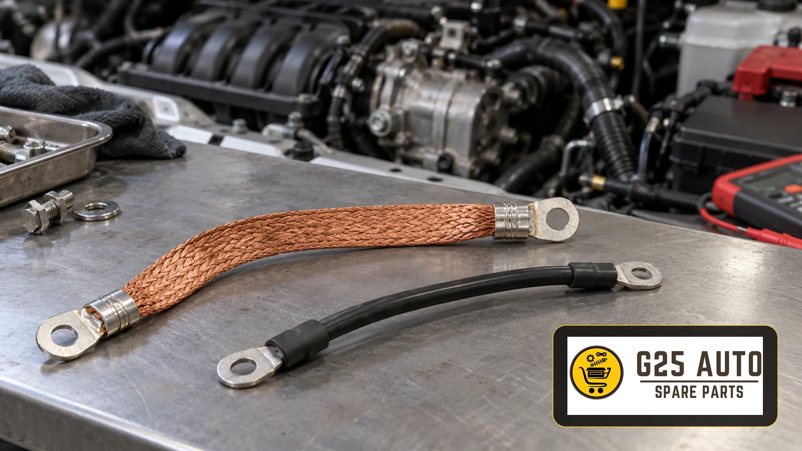
The engine-to-chassis ground cable provides an electrical return connection between the engine and the vehicle body. It may be a flexible copper braid or an insulated cable running from the engine block to a designated chassis or body connection. The location and number of connections vary with the manufacturer, engine and vehicle structure.
The Basic Function of an Engine Ground Cable
An electrical circuit needs a complete return path. In a vehicle using a negative-earth electrical system, the chassis forms part of that path. The engine and transmission are supported on mounts, so their mechanical attachment should not be assumed to provide the required electrical connection. The ground cable supplies the intended connection.
The starter, alternator and other engine electrical equipment depend on their specified return circuits. A poor connection between the engine and chassis can interfere with these circuits. Current may then take unintended paths, creating further electrical problems.
Ground Cable Construction and Materials
Ground connections can use several constructions. Flexible stranded copper braid accommodates engine movement and vibration. Flat copper strips are another form, while insulated multistrand cables may also be used. The required construction depends on the vehicle application.
The ends usually have metal ring terminals secured with bolts or nuts. The connection between conductor and terminal is as important as the visible cable. Terminal finishes and corrosion protection vary, so assess the complete assembly rather than judging it only by appearance.
Where the Connection Points Are Located
Connection points differ between vehicles. The following locations describe possible arrangements; confirm the actual points for the vehicle concerned.
Engine-Side Connection Points
A designated threaded attachment may be on the engine block or near an engine bracket. Depending on the design, the connection can be near the alternator or another bracket, or at the engine-to-transmission joint. These examples do not mean that any nearby bolt is a suitable replacement connection.
Chassis-Side Connection Points
The body-side connection may be on an inner wing or a designated structural bracket. The contact must be sound and free from corrosion or contamination that interferes with the connection. Some manufacturers provide dedicated ground studs or marked attachment points.
Fault Symptoms: When Should You Suspect a Ground Problem?
Ground cable and connection faults often appear as electrical problems. The same symptoms can have other causes, so they require assessment rather than automatic cable replacement.
Starting Problems
If the engine does not crank or turns unusually slowly, the ground path is one area to check. This is particularly relevant when the battery is charged. A weak battery, faulty starter or poor battery terminal connection can produce similar symptoms.
Charging System Problems
A poor ground connection can be associated with inadequate charging. Alternator faults, belt problems and regulator faults are other possible causes. A battery warning lamp or an abnormal charging reading therefore calls for diagnosis of the system.
Electrical Interference
Flickering instrument lights, changing headlamp brightness, radio interference and intermittent warning lamps may be associated with grounding problems. Changes when lighting or other electrical equipment is switched on can provide useful clues, but are not proof on their own.
Electronic System Errors
Intermittent control module faults, irregular injector operation or implausible sensor readings may justify checking the ground connections alongside other possible causes. A fault code alone does not establish that the ground strap is defective.
Fault Diagnosis Methods
Recognising a symptom and confirming its cause are different tasks. Work through the checks systematically.
Visual Inspection
Follow the cable from the engine to its chassis connection. Look for burning, melted insulation, broken strands, corrosion or crushing. Check both ends for looseness, rust, oxidation and dirt. Include the terminal-to-cable joints in the inspection.
Resistance Measurement with a Multimeter
A removed cable can be checked for continuity and resistance using the appropriate meter setting. Unexpected resistance or an interrupted connection may indicate damage. Interpret the result using the relevant test method rather than treating a single generic resistance figure as a universal pass limit.
Voltage Drop Testing
A voltage drop test assesses the connection while it is installed. Using the appropriate DC voltage setting, the potential difference across the relevant ground path is measured under the specified operating conditions. An excessive drop can indicate resistance in the cable or its connections; use the applicable diagnostic limits.
Testing Under Load
Checking the ground path under an electrical load can reveal a problem that is less obvious in a simple continuity check. Starting and accessory loads place different demands on the circuit. Use the vehicle test procedure to establish the load and interpret the reading.
Selecting and Verifying the Correct Part
The replacement must have the correct conductor size, length and terminal arrangement. An unsuitable cable can leave the original fault unresolved or create another problem.
Verification by OEM Part Reference
Check the original part reference against the manufacturer’s parts information. Different model years and engine variants may use different ground assemblies. A similar-looking cable does not establish compatibility.
Checking the VIN
The vehicle identification number helps a supplier identify the correct application. It is particularly useful when a model received changes during production.
Engine Code and Production Date
A model range can contain several engine options. The engine code and production date help distinguish which cable and connection arrangement applies. Verify these details with the vehicle information.
Conductor Size and Cable Length
The conductor must meet the required current capacity. Length also matters: a cable that is too short can be strained, while an unsuitable longer cable may create routing problems. Match the specified cable and its terminals rather than choosing by thickness alone.
Comparing Original and Aftermarket Parts
Both original and aftermarket replacements require application checks. The following points provide a comparison framework without assuming that either category has guaranteed performance or availability.
| Feature | Original part | Aftermarket part |
|---|---|---|
| Compatibility | Verify the correct vehicle reference | Verify the documented application |
| Quality requirements | Check the specified assembly | Check the manufacturer’s specifications |
| Availability | Confirm with the supplier | Confirm with the supplier |
| Cost | Obtain a current quotation | Obtain a current quotation |
| Warranty | Check the applicable terms | Check the applicable terms |
| Durability | Assess the relevant product information | Assess the relevant product information |
When considering an aftermarket part, review the manufacturer’s reliability, material specification and evidence for the application. General claims about equivalent quality do not replace these checks.
Points to Consider During Installation
Surface Preparation
Dirt and corrosion at the connection can prevent a sound electrical contact. Prepare the designated contact surface using the applicable repair method. Avoid assuming that every painted surface should be stripped or used as a ground point.
Connection Tightness
Secure the terminals to the specified tightening requirement. Excessive tightening can deform the terminal or damage the fastener, while a loose connection may move with vibration.
Protective Treatment
Where specified, apply the appropriate corrosion protection after making the electrical connection. Do not place an insulating treatment between the mating contact surfaces.
Cable Routing
Keep the cable away from hot exhaust components, moving parts and sharp edges. Route it without kinks or tension and allow for the intended movement of the engine.
Ground Cable Replacement Checklist
- Record the VIN, engine code and production year.
- Verify the original reference or documented replacement application.
- Check conductor size, length and terminal type.
- Prepare the appropriate tools and cleaning materials.
- Check any radio code requirements before battery disconnection.
- Disconnect the battery negative connection according to the vehicle procedure.
- Remove the old cable from its engine and chassis attachments.
- Clean the designated contact points using the appropriate method.
- Remove remaining contamination from the prepared contact surfaces.
- Position the new cable at the engine-side attachment.
- Connect the chassis side and check the routing.
- Tighten all connections to the applicable specification.
- Apply any specified external corrosion protection.
- Restore the battery connection following the vehicle procedure.
- Perform the relevant voltage drop test.
- Run the engine and check the electrical systems.
Adding Further Ground Connections
The source discusses additional ground connections, particularly on modified vehicles or where electrical problems persist. Extra cables should not replace diagnosis of the intended circuit. Any change needs verification for the actual vehicle.
Additional Engine-to-Chassis Ground
A second cable is sometimes proposed alongside the original connection. Do not assume that an additional cable will correct a defective existing terminal or cable.
Transmission-to-Chassis Ground
The transmission is mechanically joined to the engine, but its grounding arrangement depends on the design. Check the specified arrangement before proposing a separate strap.
Battery Negative to Engine Block
Where this connection is provided, inspect its condition. Damage to an existing connection calls for an appropriate repair rather than an unverified reinforcement.
Bonnet-to-Chassis Ground
A flexible connection between bonnet and body may be present in some arrangements. Confirm the vehicle requirement rather than adding one as a general remedy for electrical faults.
Frequently Asked Questions
How often should the ground cable be replaced?
This guide does not establish a universal replacement interval. Inspect the cable and its connections and investigate damage or fault symptoms. Follow any vehicle-specific maintenance requirements.
Will the vehicle start with a broken ground cable?
A broken main ground connection can prevent starting or cause difficult cranking. Other electrical problems may also occur. The result depends on the circuit and the fault.
Can a thicker cable be harmful?
A thicker conductor alone does not prove that a replacement is suitable. Confirm the required specification, terminal fit, routing and allowance for movement.
Can I replace the ground cable myself?
The work requires suitable tools, correct part identification and a sound understanding of the vehicle’s battery and connection procedures. Obtain qualified assistance if these requirements are uncertain.
How should a corroded connection be cleaned?
Use the appropriate method for the designated contact surface. The extent of corrosion and the condition of the terminal determine whether cleaning is sufficient or repair is required.
Can an unintended ground path be dangerous?
Yes. Current passing through components not intended to carry it can cause overheating and damage. Investigate the intended ground circuit when a connection fails.
Conclusion
The engine ground cable and its attachment points support the vehicle’s electrical system. Visual checks, systematic diagnosis and a correctly specified replacement help address faults without confusing symptoms with a confirmed cause.
Use the part reference, VIN, engine type and production information to verify the application. Whether selecting an original or aftermarket assembly, confirm the specification and applicable warranty terms.
Connection quality matters as much as the cable itself. Dirt, corrosion and loose terminals can compromise the ground path even when the conductor appears sound. Correct preparation, routing and verification complete the repair.