
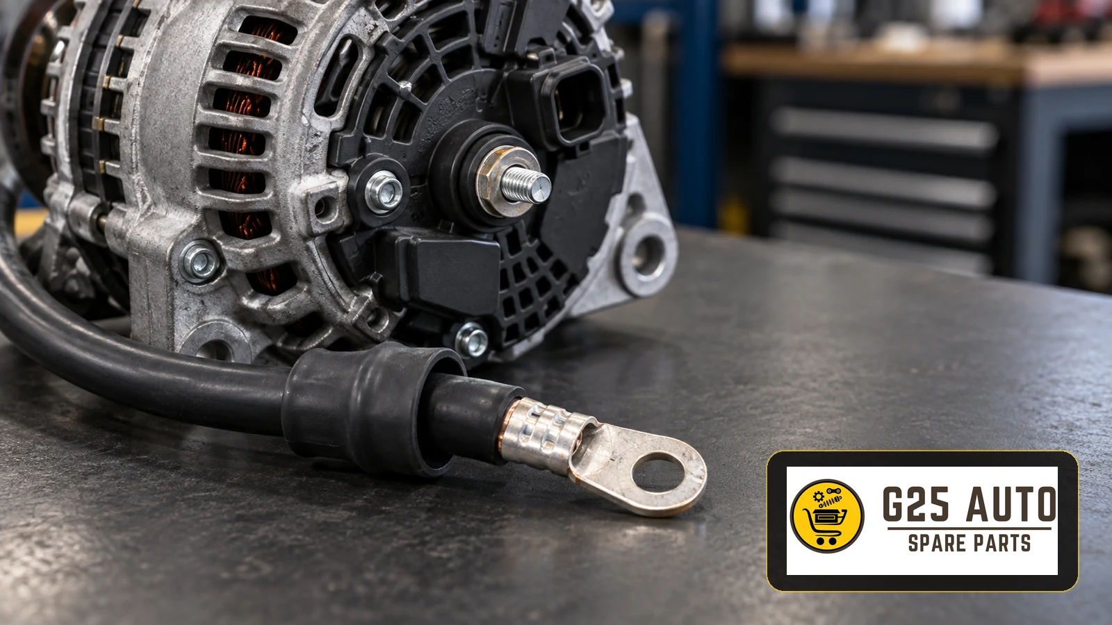
An alternator charging cable or terminal should be replaced when inspection and circuit testing identify damage or an unacceptable connection loss, using a replacement confirmed for the vehicle and installed alternator. A battery warning lamp alone does not prove that the cable is faulty. For workshops and parts distributors across Europe and the Balkans, a reliable repair starts with the wiring diagram, a documented diagnosis and a parts enquiry that identifies the complete cable assembly.
Identify the main output connection
The main charging cable connects the alternator output, commonly identified as B+, to the vehicle’s positive supply network. Its route may include a distribution point, starter connection or protective device, depending on the installation. Trace the actual circuit rather than assuming a direct cable to the battery. The smaller regulator, sensing or communication connector serves a different purpose and must be identified separately.
Record the cable route, branch connections, protective boot, supports and terminal orientation before dismantling. Photographs of the installed arrangement help the workshop and supplier discuss the same component. Insulation colour and the appearance of a ring terminal are useful observations, but neither confirms its electrical specification or application.
Separate symptoms from a confirmed cable fault
Look for physical evidence
With the vehicle safely shut down, inspect accessible insulation, terminal protection and securing points. Record corrosion, exposed strands, damaged crimps, chafing, melting or discolouration. A heat-damaged connection requires investigation of the mating terminal as well as the cable end. Replacing the cable while leaving a damaged alternator output stud can leave the fault unresolved.
Do not assess a suspect connection by touching it during operation. Stop testing if there is smoke, arcing or severe heat damage, and make the installation safe before further work. Evidence of fluid contamination or abrasion should also prompt inspection of the surrounding area, so the replacement is not exposed to the same cause.
Test the circuit under the specified conditions
DENSO recommends checking battery condition and inspecting connections before judging alternator performance. Its troubleshooting guidance also calls for voltage-drop checks on both the positive circuit and the ground return. A poor engine or body ground can resemble a charging cable problem. Investigate fuses and fusible links where they form part of the circuit.
A qualified technician should follow the vehicle test procedure to compare the alternator output connection and battery positive connection under the prescribed load. Record the measurement points, operating conditions and result. If the loss is excessive, sectional checks can help distinguish a cable fault from a connection or distribution-point fault. Use the manufacturer’s limits rather than importing a single threshold into every application.
A continuity beep alone cannot demonstrate that a cable will perform correctly under charging load. Treat resistance checks as part of the specified diagnostic process, on an appropriately isolated circuit, rather than as a substitute for assessing the working connection.
Account for controlled charging systems
HELLA’s start-stop charging-system guidance describes an example in which the engine control unit communicates with the alternator regulator and diagnostic data includes battery condition and charging information. This matters when interpreting a voltage reading: a single idle measurement should not automatically be treated as proof of failure.
Identify the system fitted to the vehicle and consult its diagnostic instructions. Where supported, compare relevant requested and actual values and investigate stored faults. Do not confuse an output-cable problem with a control or communication fault, and do not apply a conventional charging-voltage range to every managed system.
Prepare a precise replacement enquiry
Give the supplier the VIN, engine identification, relevant production information and identification from the installed alternator. Include readable cable markings and photographs of every branch and termination. Ask for confirmation against the applicable catalogue entry, including any documented supersession. A vehicle model name by itself is insufficient detail for approving the order.
Request evidence for the complete assembly: conductor specification, insulation suitable for its location, cable length, terminal geometry, protective covers, branches and any integrated protection. Check which clips, sleeves or fasteners are included. Do not select a substitute solely because its eyelet fits the stud, or assume that a thicker-looking cable is an approved upgrade.
If a terminal-only repair is proposed, first establish whether the vehicle manufacturer permits it. Obtain the approved terminal, conductor preparation, crimp tooling and sealing procedure. Where no supported repair method exists, confirm the appropriate assembly replacement instead. Commercial availability and visual similarity are not evidence of a validated repair.
Control installation and verify the result
Follow the vehicle’s shutdown, battery isolation and reconnection procedure before releasing the main output connection. DENSO’s replacement guidance warns against disconnecting a battery while the engine is running. Allow for vehicle-specific waiting periods and additional power sources; this guide does not replace their service instructions.
Use the specified terminal hardware, assembly order and tightening torque. Do not copy a torque value from another alternator. Inspect the stud and its insulation, and use the prescribed method to avoid disturbing the terminal assembly. Apply cleaning or protective products only where the relevant instructions permit them.
Restore the documented routing, supports and covers, checking clearance from moving parts, heat and sharp edges. After reconnection, repeat the required charging-system and voltage-drop checks under comparable conditions. Save the before-and-after results with the repair record, including any unresolved fault. A cleared warning lamp alone is not a complete handover check.
Workshop and procurement checklist
- Identify the vehicle, installed alternator and correct wiring diagram.
- Distinguish the main output lead from control and sensing wiring.
- Document cable, terminal, ground and protection-device checks.
- Record loaded test conditions and vehicle-specific acceptance limits.
- Confirm the complete replacement application and included hardware.
- Obtain an approved method before authorising a terminal repair.
- Restore routing, supports, insulation and terminal protection.
- Retest the system and retain the results for handover.
Frequently asked questions
Does a battery warning lamp mean the charging cable needs replacing?
No. Inspect and test the charging system to distinguish a cable or connection fault from battery, alternator, ground or control-system problems.
Can any ring terminal of the correct hole size be used?
No. Confirm the conductor, terminal design, repair method and application documentation. Hole size alone cannot establish suitability.
Is there a universal cable replacement interval?
Use the vehicle maintenance requirements and the component’s assessed condition. Do not assign a fixed service life without supporting application information.
Must the alternator also be replaced?
That depends on the diagnosis and the condition of its output connection. A cable fault does not automatically require alternator replacement, but related damage must be assessed.
Technical references
DENSO alternator troubleshooting; HELLA charging-system service guidance; DENSO starter and alternator technical manual.