
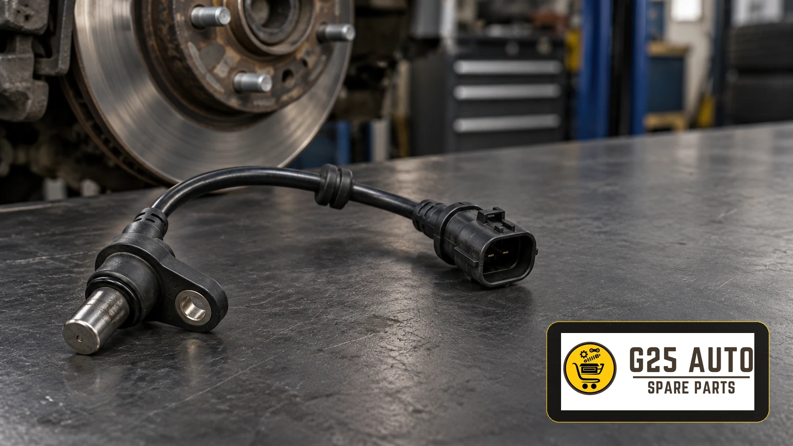
An ABS wheel-speed sensor measures wheel rotation and supplies the braking control system with information used by anti-lock braking, traction control and stability functions. When a warning or implausible speed signal appears, diagnose the sensor circuit and its rotating target before ordering a replacement. For European and Balkan workshops, a reliable repair starts with evidence from the vehicle and an application-verified parts selection.
What can an ABS sensor fault look like?
An ABS warning lamp, related stability-system warnings or unexpected brake intervention can point towards a wheel-speed signal problem. These symptoms do not identify the failed part. Wiring damage, a poor connection, a damaged target ring or bearing problems may create similar complaints. A fault code naming a wheel position is a starting point for investigation, rather than proof that a new sensor is required.
Record when the concern occurs and whether recent brake, bearing or suspension work preceded it. Treat abnormal braking as a safety concern: follow the vehicle manufacturer’s warning instructions and have the vehicle assessed by a qualified technician before deciding whether it can be moved.
Identify the sensor technology before testing
A passive inductive sensor generates an electrical signal as its target rotates. An active sensor needs a power supply and processes the changing magnetic field electronically. Depending on the application, the target may be a toothed ring or a magnetic encoder associated with the wheel bearing. Confirm the fitted design from technical information.
External appearance and wire count are insufficient to distinguish some active and passive sensors. Do not apply a resistance test to an active sensor: an unsuitable test can damage it. Use the manufacturer’s circuit identification, connection method and expected signal characteristics.
A diagnosis that supports the parts decision
Capture the electronic evidence
Use diagnostic equipment that communicates with the vehicle’s ABS controller. Save fault codes and relevant operating data before clearing them. Compare wheel-speed readings under the manufacturer’s prescribed conditions. Note which signal differs and when the difference appears; this gives the technician a specific circuit to investigate.
Inspect the complete signal path
Inspect wiring and connectors, then the sensor mounting and rotating target. Check for chafing, corrosion, displaced clips and damage. Consider bearing condition and the history of recent work. Where electrical testing is required, follow the vehicle-specific procedure with suitable equipment. A new sensor will not correct an unresolved circuit or target fault.
Replacement selection checklist for B2B buyers
Prepare a documented enquiry so the supplier can distinguish vehicle variants and wheel positions. This is particularly useful when a workshop or distributor handles mixed European fleets across several markets.
- Provide the VIN, model, production date and relevant engine or drivetrain details.
- State the axle and side, together with any braking-system variant requested by the catalogue.
- Record the existing part reference and check current application and supersession information.
- Confirm sensor technology, connector configuration, mounting arrangement and cable routing.
- Use photographs to clarify the existing installation, while keeping catalogue verification as the basis for selection.
- Specify the diagnosed component: sensor, wiring repair, separate ring or bearing/hub assembly.
- Confirm required fitting hardware and obtain the applicable installation instructions.
Ask for a documented application match rather than accepting a similar photograph or vehicle name. For either an OE-branded or independent aftermarket part, check the manufacturer’s application listing and the supplied product identification. Price, packaging or a broad quality claim alone cannot establish compatibility.
For a quotation through G25 AUTO, keep the vehicle identifiers, required position and workshop findings together in one enquiry. Ask for written confirmation of the proposed reference and what the supplied assembly includes before approving the order. Request current commercial terms separately for the actual requirement.
Installation and repair verification
A qualified technician should follow the vehicle and component instructions for removal, mounting, cable retention and tightening. Route the cable through the specified clips and confirm that the connector is secure. Avoid cable tension or contact with moving components.
After installation, carry out the prescribed diagnostic and functional checks, review wheel-speed data and check for returning faults. Complete any guided service procedure required by the application. Record the fitted reference and verification outcome in the job file; an extinguished warning lamp alone is an incomplete repair record.
Frequently asked questions
Does a sensor fault code mean the sensor must be replaced?
No. Diagnose the circuit, connections and target before deciding which component has failed.
Can two similar-looking sensors be interchanged?
Appearance is insufficient. Confirm the exact application, position and reference before fitting.
Must all wheel-speed sensors be replaced together?
Base the repair scope on diagnosis and the applicable service information. Do not assume that one fault requires replacement of every sensor.
Is coding or calibration always necessary?
Check the procedure for the specific vehicle and component. Avoid a blanket assumption for either active or passive sensors.