
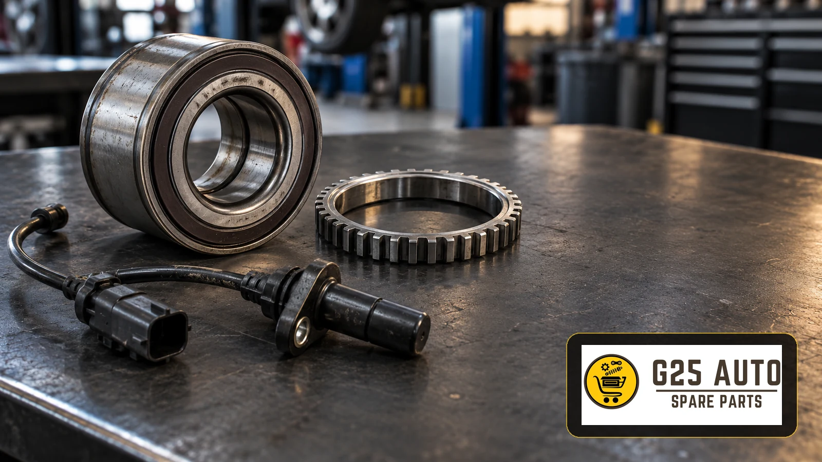
An ABS reluctor ring or magnetic encoder provides the rotating reference that a wheel-speed sensor reads. When the ring, sensor or associated wiring is damaged, the ABS control unit may receive an unreliable wheel-speed signal. For European and Balkan workshops, the practical priority is to identify the fitted system, diagnose the complete signal path and verify the replacement by vehicle application before ordering.
Toothed ring or magnetic encoder: identify the system first
A conventional reluctor ring has visible metal teeth. A magnetic encoder uses alternating magnetic poles and may be incorporated into a wheel-bearing seal, so its working surface can appear smooth. The two designs must not be treated as interchangeable simply because their outside dimensions look similar.
Passive inductive sensors generate a signal as the target passes them. Active sensors require an electrical supply and use electronics to process the changing field. Depending on the system, an active sensor can work with a magnetic encoder or a steel target. Establish the actual vehicle configuration from the parts catalogue and repair information instead of assuming the sensor type from appearance alone.
Symptoms identify a problem, not the failed component
An ABS warning lamp, a stability-control warning or unexpected ABS intervention can justify investigating wheel-speed signals. None proves that the sensor itself has failed. A damaged ring, contamination, corrosion around a sensor mounting, a poor connector or a wiring defect can produce overlapping symptoms.
Record the reported conditions and diagnostic trouble codes before clearing anything. Ask whether the concern began after bearing, driveshaft or suspension work. That history helps the technician target inspection without turning a recent repair into an assumed diagnosis.
A workshop diagnosis before a purchase order
Compare electronic evidence with physical inspection
Use a diagnostic tool suitable for the vehicle to compare wheel-speed live data under controlled conditions. Inspect the indicated corner, sensor cable routing, connector and target surface using the vehicle manufacturer’s procedure. Check the bearing and its mounting where relevant. Any electrical measurement must match the identified sensor technology; a generic resistance test is not a universal test for active sensors.
For an integrated magnetic encoder, an appropriate viewing card can help locate the encoder side and reveal irregularities in the pole pattern. Protect the seal from scratches, dirt and magnetic tools. Use the specified inspection and cleaning method rather than abrasive treatment or an assumed universal sensor gap.
Parts enquiry checklist for professional buyers
A useful enquiry gives the supplier enough information to distinguish the sensor, separate target ring and complete bearing or hub assembly. For mixed European vehicle fleets, collect the following before requesting a match through g25auto.com:
- VIN, model, production date and relevant engine or drivetrain configuration.
- Axle position and side, plus the braking or stability-system variant where the catalogue requires it.
- Existing OE reference, checked against the current application catalogue and any supersession information.
- Whether the required target is a separate toothed ring or part of a bearing or hub assembly.
- Sensor connector, cable routing and mounting details, supported by clear photographs when useful.
- The diagnosis and the exact components required, including any application-specific fitting hardware.
Confirm the selected item against the application data before fitting. A shared vehicle name, similar connector or matching photograph does not establish compatibility. Avoid substituting a loose ring where the manufacturer specifies replacement of an integrated assembly.
Installation and repair verification
Installation should be carried out by a qualified technician using the specified tools, orientation, tightening procedure and replacement hardware. On bearings with a magnetic encoder, confirm that the encoder faces the sensor as required by the application. Protect the encoder seal and keep installation force away from sensitive surfaces.
After the repair, follow the manufacturer’s diagnostic and functional checks. Review fault memory and wheel-speed data, confirm warning-lamp behaviour and perform any required controlled road test when the vehicle is safe to test. A warning lamp going out alone is insufficient evidence that an intermittent signal problem has been resolved.
Frequently asked questions
Does a wheel-speed fault mean the sensor needs replacing?
No. The target ring, bearing, wiring, connector and sensor must be assessed together. Replace the component identified by diagnosis.
Can the ABS ring be ordered separately?
Sometimes. Other applications integrate the encoder into a bearing or hub. The vehicle catalogue and repair instructions determine the serviceable assembly.
Is a magnetic encoder visibly toothed?
Not necessarily. A magnetic encoder can have a smooth seal surface. Identify it with suitable inspection equipment and application information, rather than looking for metal teeth.