
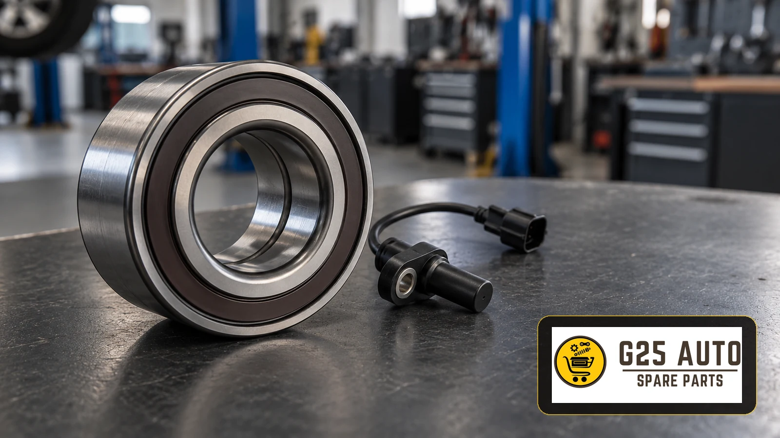
An ABS magnetic encoder ring provides the rotating magnetic pattern read by a compatible wheel-speed sensor. If that pattern is damaged, contaminated or facing away from the sensor after bearing replacement, the ABS system can receive unreliable wheel-speed information. Confirm the fault before ordering: the correct repair may involve cleaning, a separately serviceable ring or a complete bearing or hub assembly, depending on the vehicle design.
Identify the target before selecting a replacement
A magnetic encoder and a toothed reluctor ring serve a similar purpose but are different components. The magnetic version uses alternating poles, often incorporated into a bearing seal; these poles are not visible metal teeth. A toothed ring presents a physical tooth pattern. Do not select a replacement solely because a catalogue description calls both items an ABS ring.
For European and Balkan workshops, a useful first question is what the vehicle manufacturer actually supplies for the affected wheel position. Check the application catalogue to establish whether the encoder is serviced separately or supplied within a larger assembly. A photograph of an apparently similar ring cannot establish its suitability.
Separate encoder faults from sensor and wiring faults
An ABS or stability-control warning, intermittent wheel-speed reading or unwanted regulation can justify investigation, but none identifies the encoder as the failed part. Record when the complaint occurs and whether it began after bearing, driveshaft or brake work. That repair history gives the technician a focused starting point without turning a suspicion into a parts order.
Use a diagnostic sequence
- Read the ABS fault memory with equipment that supports the installed system, and retain the complete fault description.
- Compare individual wheel-speed data under the vehicle manufacturer’s prescribed test conditions.
- Inspect the sensor cable, connector, mounting position and bearing condition alongside the encoder.
- Check the electrical supply and signal using the correct circuit information and suitable equipment. Do not apply a resistance test to an active sensor.
Where accessible and appropriate, an encoder detector card can help identify the magnetic face and reveal an irregular pole pattern. A clean-looking surface alone does not prove that the magnetic pattern is intact. If a fault appeared immediately after replacement, verify the fitted part and its orientation before condemning another sensor.
Decide whether cleaning or replacement is justified
Metallic debris can interfere with some magnetic encoders. Cleaning is appropriate only when the vehicle-specific instructions permit access and provide a suitable method. Protect the seal and avoid magnetic tools. Do not scrape the encoder, expose it to an improvised chemical treatment or assume that every warning can be solved by removing dirt.
Physical damage, a defective pole pattern or an incorrectly specified assembly calls for a different repair decision. Establish the serviceable unit from the application documentation. Do not attempt to substitute a loose ring for an integrated encoder seal unless the relevant parts and repair instructions explicitly support that operation.
Procurement checklist for trade enquiries
Give the supplier a complete application record. This is particularly helpful when the workshop and purchasing team work in different countries or use different names for the same component.
- Vehicle identification number, production details and the precise axle and wheel position.
- Relevant drivetrain, chassis or ABS variant details requested by the catalogue.
- The existing part reference, where legible, checked against the current application listing.
- Confirmation of magnetic encoder or toothed target, and the required serviceable assembly.
- Documented dimensions, pole or tooth configuration and other fitment criteria where the listing requires them.
- Kit contents and any additional hardware specified for the repair.
Ask for written confirmation against that application record. A shared model name, matching outside diameter or general quality claim is insufficient evidence of compatibility. Keep the supplier’s reference and the workshop’s diagnosis together so that the receiving technician can check the delivered component before dismantling continues.
Protect the encoder during installation
Keep the new bearing protected until fitting and keep magnets away from the encoder. On a bearing with a single magnetic face, that face must be presented to the sensor as specified for the application. Verify this before pressing the bearing into position.
Use the fitting tools and load path specified for the bearing design; never transmit pressing force through the encoder seal. Follow the vehicle and component instructions for fasteners, tightening and sensor clearance. There is no universal air-gap or torque value suitable for every assembly.
Record the repair verification
After assembly, follow the prescribed fault-clearing and verification procedure, compare wheel-speed readings again and check for returning faults. Complete any required road test under controlled, appropriate conditions. Do not deliberately provoke wheel lock on public roads to demonstrate ABS operation. Retain the before-and-after findings with the fitted part reference.
Frequently asked questions
Does a wheel-speed fault code prove the ring is faulty?
No. The code identifies a diagnostic concern. The sensor, circuit, mounting and rotating target still need assessment before a component is selected.
Must the sensor and encoder be replaced together?
Not automatically. Replace the components justified by diagnosis and the application’s service arrangement. An integrated encoder may require a bearing or hub assembly even when the separate sensor remains serviceable.
Can an identical-looking bearing have a different encoder arrangement?
Appearance does not confirm fitment. Verify the application reference and encoder specification, then check the supplied part before installation.
Is it acceptable to ignore an ABS warning?
No. Follow the vehicle’s warning instructions and arrange qualified diagnosis. Abnormal braking or an additional brake warning requires immediate assessment of whether the vehicle can be moved safely.
Technical references
Diagnostic principles: HELLA wheel-speed sensor guidance. Encoder handling and orientation: NSK wheel-bearing installation guidance. Debris-related faults are illustrated for specific applications in GM service bulletin PIC5428G; its procedures must not be applied universally.